Hi everyone,
We’d like to share a small project using the AgileX PiPER Robotic Arm to explore forward and inverse kinematics.
The project demonstrates how to calculate FK/IK using Eigen and control the robot with interactive markers in RVIZ.
It’s a hands-on example showing how to verify FK accuracy, solve IK with joint limits, and interact with the arm in both simulation and on the real robot.
This is a lightweight, practical demo for anyone interested in manipulator kinematics or human-robot interaction.
Abstract
This chapter achieves the forward kinematics solution and the Jacobian method for inverse kinematics solution of the AgileX PiPER Robotic Arm based on the Eigen linear algebra library, as well as the implementation of the custom interactive marker interactive_marker_utils.
Tags
Forward Kinematics, Jacobian Method for Inverse Kinematics, RVIZ Simulation, Manipulator DH (Denavit-Hartenberg), Interactive Marker, AgileX PiPER
Code Repository
GitHub Link: https://github.com/agilexrobotics/Agilex-College.git
Function Demonstration


Preparation Before Use
Hardware Preparation
- AgileX Robotics PiPER Robotic Arm
Software Environment Configuration
- For the deployment of the PIPER arm driver: piper_sdk
- For the deployment of the PIPER arm ROS control node: piper_ros
- Install the Eigen linear algebra library:
sudo apt install libeigen3-dev
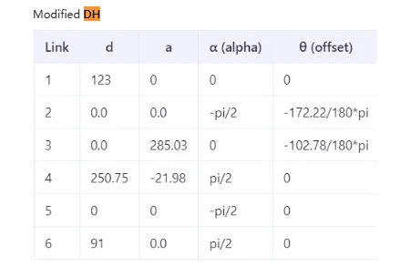
Preparation of DH Parameters Table and Joint Limits for AgileX PiPER
The modified DH parameters table and joint limits of PIPER can be found in the AgileX PIPER User Manual:

Forward Kinematics Calculation (FK)
The calculation process of forward kinematics (FK) is to compute the pose of a certain joint of the robotic arm in the 3D world based on the angle values of each joint. This article takes the last rotating joint (joint6) of the robotic arm as an example.
Preparation of DH Parameters
- Construct the forward kinematics calculation program according to PiPER’s DH parameters table. Based on the modified DH parameters table of AgileX PiPER in Section 1.3, the following parameters are obtained:
//modified DH Parameter [alpha, a, d, theta_offset]
dh_params_ = {
    {0,         0,          0.123,      0},                     // Joint 1
    {-M_PI/2,   0,          0,          -172.22/180*M_PI},      // Joint 2
    {0,         0.28503,    0,          -102.78/180*M_PI},      // Joint 3
    {M_PI/2,    -0.021984,  0.25075,    0},                     // Joint 4
    {-M_PI/2,   0,          0,          0},                     // Joint 5
    {M_PI/2,    0,          0.091,      0}                      // Joint 6
};
To convert to standard DH, the following conversion rules can be referred to:
- From Standard DH → Modified DH:
αᵢ₋₁(Standard) = αᵢ(Modified)
aᵢ₋₁(Standard) = aᵢ(Modified)
dᵢ(Standard) = dᵢ(Modified)
θᵢ(Standard) = θᵢ(Modified) - From Modified DH → Standard DH:
αᵢ(Standard) = αᵢ₊₁(Modified)
aᵢ(Standard) = aᵢ₊₁(Modified)
dᵢ(Standard) = dᵢ(Modified)
θᵢ(Standard) = θᵢ(Modified)
Standard DH Parameters After Conversion:
// Standard DH  [alpha, a, d, theta_offset]
dh_params_ = {
    {-M_PI/2,   0,          0.123,      0},                     // Joint 1
    {0,         0.28503,    0,          -172.22/180*M_PI},      // Joint 2
    {M_PI/2,    -0.021984,  0,          -102.78/180*M_PI},      // Joint 3
    {-M_PI/2,   0,          0.25075,    0},                     // Joint 4
    {M_PI/2,    0,          0,          0},                     // Joint 5
    {0,         0,          0.091,      0}                      // Joint 6
};
- Preparation of DH Transformation Matrix
- Modified DH Transformation Matrix:

Rewritten in Eigen:
T << cos(theta),            -sin(theta),            0,             a,
     sin(theta)*cos(alpha), cos(theta)*cos(alpha), -sin(alpha), -sin(alpha)*d,
     sin(theta)*sin(alpha), cos(theta)*sin(alpha),  cos(alpha),  cos(alpha)*d,
     0,                     0,                      0,             1;
- Standard DH Transformation Matrix:

Rewritten in Eigen:
T << cos(theta), -sin(theta)*cos(alpha),  sin(theta)*sin(alpha), a*cos(theta),
     sin(theta),  cos(theta)*cos(alpha), -cos(theta)*sin(alpha), a*sin(theta),
     0,           sin(alpha),             cos(alpha),            d,
     0,           0,                      0,                     1;
- Implementation of the Key Function
computeFK()
For the complete code, see the repository:
https://github.com/agilexrobotics/Agilex-College.git
Eigen::Matrix4d computeFK(const std::vector<double>& joint_values) {
    //Check the number of input joints (at least six)
    if (joint_values.size() < 6) {
        throw std::runtime_error("Piper arm requires at least 6 joint values for FK");
    }

    //Initialize the identity matrix as the initial transformation
    Eigen::Matrix4d T = Eigen::Matrix4d::Identity();

// For each joint:
// Calculate actual joint angle = input value + offset
// Get fixed parameter d value
// Calculate the transformation matrix for the current joint and accumulate it to the total transformation
    for (size_t i = 0; i < 6; ++i) {
        double theta = joint_values[i] + dh_params_[i][3];  // θ = joint_value + θ_offset
        double d = dh_params_[i][2];                       // d = d_fixed (if it's rotating joint)

        T *= computeTransform(
            dh_params_[i][0],  // alpha
            dh_params_[i][1],  // a
            d,                 // d
            theta              // theta
            );
    }

    //Return to final transformation matrix
    return T;
}
Verification of FK Calculation Accuracy
- Start the forward kinematics verification program:
ros2 launch piper_kinematics test_fk.launch.py
- Start the RVIZ simulation, enable TF tree display, and check whether the pose of
link6_from_fk(end of the arm computed by FK) coincides withlink6(pose fromjoint_state_publisher):
ros2 launch piper_description display_piper_with_joint_state_pub_gui.launch.py
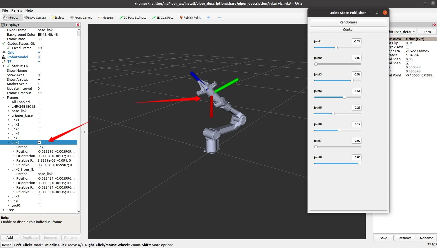
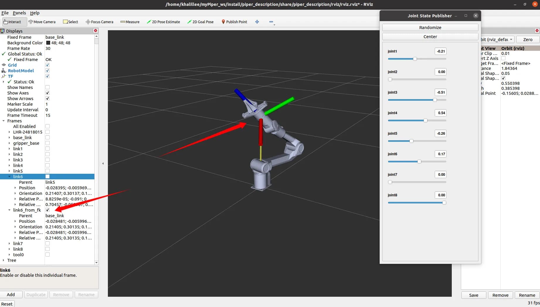
The coincidence is very high; the error between link6_from_fk and link6 is basically within four decimal places.
Inverse Kinematics Solution (IK)
Inverse kinematics calculates the joint angles required for the manipulator to reach a given target pose.
Confirmation of Joint Limits
- Each joint limit must be confirmed to ensure the IK solution does not exceed the robot’s physical limits.
- The limits for the PiPER Robotic Arm (from Section 1.3) are:
- The joint limit matrix in code:
std::vector<std::pair<double, double>> limits = {
    {-154/180*M_PI, 154/180*M_PI},    // Joint 1
    {0, 195/180*M_PI},                 // Joint 2
    {-175/180*M_PI, 0},                // Joint 3
    {-102/180*M_PI, 102/180*M_PI},     // Joint 4
    {-75/180*M_PI, 75/180*M_PI},       // Joint 5
    {-120/180*M_PI, 120/180*M_PI}      // Joint 6
};
Brief Steps for Implementing IK Using Jacobian Matrix Method
Solution Process
-
Compute the pose error
e: difference between current pose and target pose (6D: 3 position + 3 orientation). -
Check if
eis below threshold:- Yes: return current
θas solution. - No: continue iteration.
- Yes: return current
-
Calculate the Jacobian matrix
J(6×6). -
Compute damped pseudoinverse:
Where λ is the damping factor to avoid numerical instability near singularities.
- Compute joint increment:
- Update joint angles:
-
Apply joint limits.
-
Normalize angles to standard range (e.g., [-π, π]).
-
Check maximum iteration:
- No: go back to step 2.
- Yes: throw an unconverged error.
Key Function computeIK()
std::vector<double> computeIK(
    const std::vector<double>& initial_guess,
    const Eigen::Matrix4d& target_pose,
    bool verbose = false,
    Eigen::VectorXd* final_error = nullptr)
{
    if (initial_guess.size() < 6) {
        throw std::runtime_error("Initial guess must have at least 6 joint values");
    }

    std::vector<double> joint_values = initial_guess;
    Eigen::Matrix4d current_pose;
    Eigen::VectorXd error(6);
    bool success = false;

    for (int iter = 0; iter < max_iterations_; ++iter) {
        current_pose = fk_.computeFK(joint_values);
        error = computePoseError(current_pose, target_pose);

        if (verbose) {
            std::cout << "Iteration " << iter << ": error norm = " << error.norm()
                      << " (pos: " << error.head<3>().norm()
                      << ", orient: " << error.tail<3>().norm() << ")\n";
        }

        if (error.head<3>().norm() < position_tolerance_ &&
            error.tail<3>().norm() < orientation_tolerance_) {
            success = true;
            break;
        }

        Eigen::MatrixXd J = use_analytical_jacobian_ ?
            computeAnalyticalJacobian(joint_values, current_pose) :
            computeNumericalJacobian(joint_values);

        Eigen::MatrixXd Jt = J.transpose();
        Eigen::MatrixXd JJt = J * Jt;
        JJt.diagonal().array() += lambda_ * lambda_;
        Eigen::VectorXd delta_theta = Jt * JJt.ldlt().solve(error);

        for (int i = 0; i < 6; ++i) {
            joint_values[i] = std::clamp(joint_values[i] + delta_theta(i),
                                         joint_limits_[i].first,
                                         joint_limits_[i].second);
        }

        normalizeJointAngles(joint_values);
    }

    if (!success) {
        throw std::runtime_error("IK did not converge within maximum iterations");
    }

    if (final_error != nullptr) {
        current_pose = fk_.computeFK(joint_values);
        *final_error = computePoseError(current_pose, target_pose);
    }

    return joint_values;
}
Using interactive_marker to Publish 3D Target Points
- Install ROS2 dependency packages:
sudo apt install ros-${ROS_DISTRO}-interactive-markers ros-${ROS_DISTRO}-tf2-ros
- Start
interactive_marker_utilsto realize the publication of 3D space target points:
ros2 launch interactive_marker_utils marker.launch.py
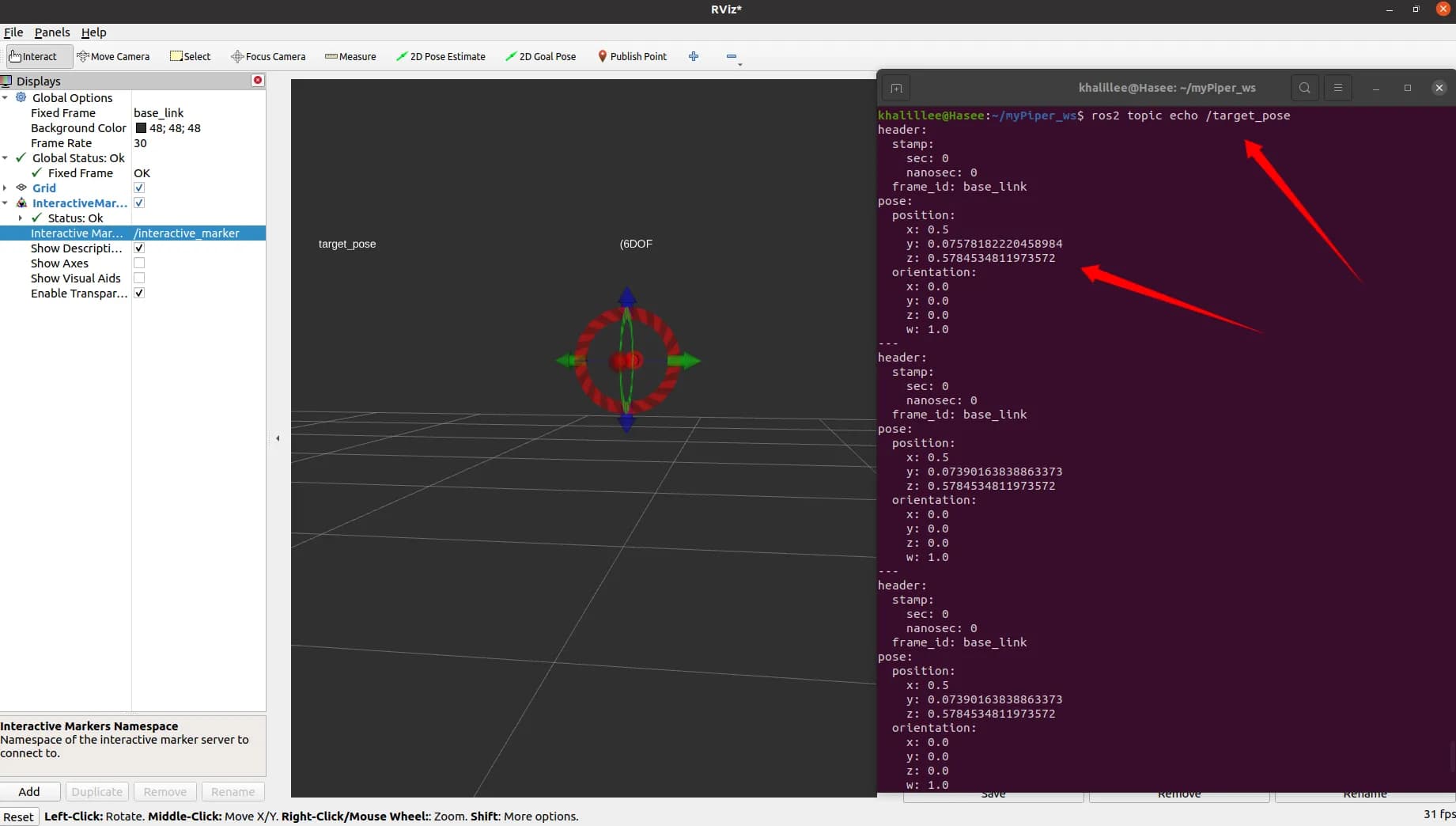
- Start RVIZ2 to observe the Marker:
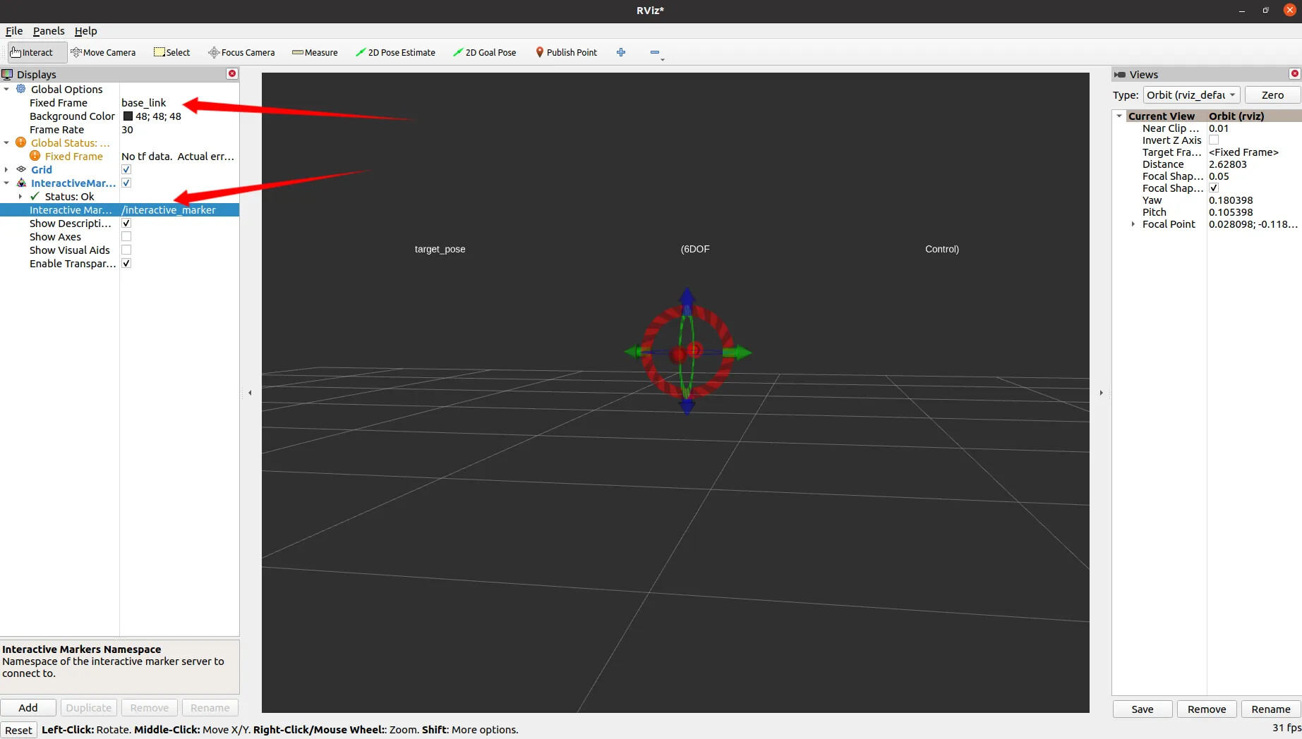
4.Drag the Marker and use ros2 topic echo to observe whether the target point published by the Marker changes
Verify IK Correctness in RVIZ via interactive_marker
- Start the RVIZ simulation demo of AgileX PiPER. Since there is no
joint_state_publisherat this time, the model will not be displayed correctly:
ros2 launch piper_description display_piper.launch.py

- Next, start the IK node and the
interactive_markernode (in the same launch file). After successful startup, the robotic arm can be displayed normally:
ros2 launch piper_kinematics piper_ik.launch.py

- Use the
interactive_markerto control the robotic arm for IK solution:


-
By dragging the
interactive_marker, it can be seen that the IK successfully solves the angle of each joint
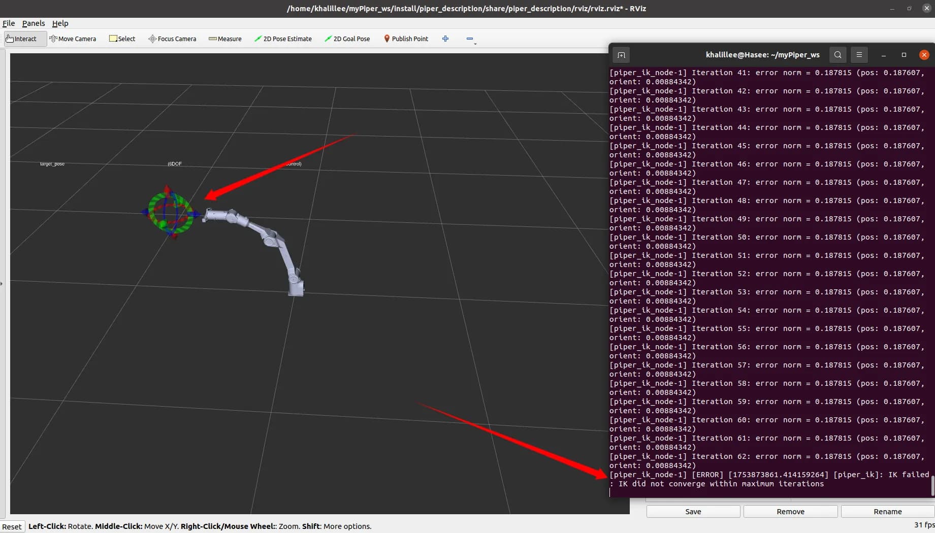
-
If the
interactive_markeris dragged to a position where the solution is impossible, an exception will be thrown

Verify IK on the Actual PiPER Robotic Arm
- First, start the script for connecting to the CAN communication of PIPER
cd piper_ros
./find_all_can_port.sh
./can_activate.sh
- Start the actual machine control node of PiPER
ros2 launch piper my_start_single_piper_rviz.launch.py
- Next, start the IK node and the
interactive_markernode (in the same launch file). It can be seen that the robotic arm moves to the HOME position
ros2 launch piper_kinematics piper_ik.launch.py
- Drag the
interactive_markerand observe the movement of the PIPER Robotic Arm
That’s a wrap!
With this setup, you can:
- Compute and verify FK and IK for the PiPER arm.
- Use
interactive_markerto move the arm in 3D space. - Safely experiment in both simulation and on the actual robot.
Hope this inspires your own projects or experiments with PiPER!